1. Preparation before installation
Confirm the integrity of the equipment: Check whether the appearance of the APL312 limit switch box is damaged and whether the accessories are complete, including the switch box body, mounting bracket, fixing bolts, wiring terminals, etc.
Prepare installation tools: Prepare common tools such as screwdrivers, wrenches, pliers, etc. to ensure that the tool specifications are suitable for the installation parts.
Verify the installation position: According to the actual use requirements, determine the appropriate installation position, which should be convenient for operation and maintenance and can accurately detect the position change of the controlled equipment.
2. Install the switch box body
Fix the mounting bracket: If the switch box is equipped with a mounting bracket, first fix the bracket in the selected position. Use a screwdriver or wrench to tighten the fixing bolts to ensure that the bracket is firm and does not shake.
Install the switch box: Install the APL312 limit switch box on the fixed bracket, align it with the mounting hole, and fix it with bolts. Pay attention to adjusting the angle and position of the switch box so that it can accurately sense the movement state of the detected equipment, and then tighten the bolts completely.
3. Connect the detection element
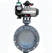
Connect the drive shaft: If the limit switch box is used to detect valves and other equipment, connect its drive shaft and the valve drive shaft coaxially through a coupling or other connector to ensure that the connection is firm and the rotation is flexible to avoid loosening or jamming.
Install the cam: According to the range of motion of the detected equipment, install and adjust the position of the cam so that the cam can accurately touch the micro switch in the switch box when the equipment moves to the set position.
4. Line connection
Open the junction box: Use a screwdriver to unscrew the screws on the junction box cover and open the junction box.
Connect the cable: Connect the external cable to the terminal block according to the control circuit requirements. According to the markings, distinguish between normally open and normally closed contacts and common terminals to ensure that the wiring is correct. Generally, a screwdriver is used to tighten the screws on the terminal block to fix the cable.
Arrange the cable: After the connection is completed, arrange the cable to avoid cable entanglement and pulling, which will affect the normal operation of the equipment. Cable ties and other tools can be used to fix the cable.
5. Debugging and testing
Preliminary debugging: Turn on the power, manually operate the detected equipment, and observe whether the limit switch box operates normally and whether the switch signal is accurately fed back.
Fine adjustment: If the position detection is inaccurate or the signal feedback is abnormal, readjust the cam position, transmission shaft connection, and other components until the limit switch box can accurately detect the device position and output the correct signal.
If you are interested in learning more about the installation steps of the APL312 Limit Switch Box, we sincerely welcome you to visit our carefully crafted website, www.xmvalveactuator.com!