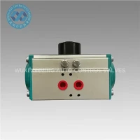
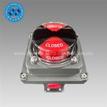
In most industrial automation projects, the pneumatic rack and pinion actuator is one of those components that engineers tend to "assume they already understand" - until something goes wrong in the field or a valve doesn't behave as expected.
At WUXI XINMING AUTO-CONTROL VALVES INDUSTRY CO., LTD., we've seen this happen more than once during commissioning or retrofit projects. A valve works perfectly in the workshop test, but once installed on-site with real air supply conditions, torque demand, and piping stress, the behavior changes. That's usually when the actuator design suddenly becomes a real topic instead of just a catalogue item.
So let's explain it in a practical way: what it is, how it works, and what actually matters in real projects.
What exactly is a Pneumatic Rack and Pinion Actuator?
A pneumatic rack and pinion actuator is a quarter-turn valve actuator that converts compressed air energy into rotary motion.
Inside the actuator, there are three key mechanical elements:
- A piston system
- A rack mechanism
- A central pinion gear
The basic idea is simple: linear motion becomes rotary motion.
But in real engineering applications, the simplicity hides a lot of design details that directly affect torque output, lifetime, and stability.
How does it actually work in real operation?
When compressed air enters the actuator chamber, it pushes the pistons outward. These pistons are connected to rack teeth, which engage with the central pinion gear.
As the racks move in opposite directions, the pinion rotates. That rotation is transmitted directly to the valve stem - usually for:
- Ball valves
- Butterfly valves
- Plug valves
In a double acting configuration, air is used for both opening and closing.
In a spring return configuration, air drives the motion in one direction, while internal springs provide the return stroke.
On paper, this sounds straightforward. In real systems, however, the air quality, pressure stability, and load condition often matter more than the mechanism itself.
A real-world issue we often see in the field
One project that stayed in our memory was a water treatment plant retrofit.
The customer initially installed pneumatic rack and pinion actuators from different suppliers on butterfly valves across filtration and dosing lines. During commissioning, everything looked fine at low cycle testing.
But after the system started running continuously, a few problems appeared:
Some valves responded slower than expected
A few actuators did not fully reach end position under low air pressure conditions
Torque inconsistency appeared between identical valve sizes
When we checked on-site, the issue was not the valve itself - it was a combination of:
fluctuating instrument air pressure
oversized valve torque requirement due to seat friction variation
inconsistent actuator sizing across batches
This is a typical situation where the actuator is "technically correct" but "practically mismatched".
It's also why rack and pinion actuators cannot be selected purely from catalogue torque charts without considering real operating conditions.
Why rack and pinion design is so widely used
Despite its simplicity, the rack and pinion structure remains one of the most widely used designs in valve automation. The reasons are practical:
Compact structure with high torque efficiency
Suitable for quarter-turn valves
Easy to match with ISO 5211 mounting standards
Relatively predictable torque output
Works well in both small and medium automation systems
In our production experience, most customers using ball valves and butterfly valves prefer this structure because it integrates easily into existing piping systems without major modification.
Where it is typically used
In real industrial environments, pneumatic rack and pinion actuators are commonly found in:
- Water treatment systems
- Chemical dosing and mixing lines
- HVAC flow control systems
- General industrial fluid control
- Packaging and process automation lines
In many of these cases, the actuator is not the "main equipment" - but if it fails, the whole system stops behaving correctly. That's why reliability matters more than complexity.
What engineers usually care about
When we talk with engineers or procurement teams, the discussion rarely stays at "how it works". It quickly moves to practical concerns:
- What happens if air pressure drops?
- Will the actuator still reach full stroke under load?
- How stable is torque output over time?
- Can it handle misalignment or valve wear?
- How easy is maintenance in the field?
These are the questions that actually decide whether a pneumatic rack and pinion actuator is suitable for a project or not.
How we approach it at WUXI XINMING
At WUXI XINMING AUTO-CONTROL VALVES INDUSTRY CO., LTD., we don't treat pneumatic rack and pinion actuators as standalone products. We look at them as part of a complete valve automation system.
In many cases, what we recommend to customers is not just "a model", but a configuration based on:
- valve type
- required torque margin
- air supply stability
- operating frequency
- environment
This is especially important in export projects where operating conditions in the field can be very different from design assumptions.
Final thoughts
A pneumatic rack and pinion actuator is a simple mechanism in principle, but in real industrial applications, its performance depends heavily on system conditions and correct selection.
Understanding how it works is not just theoretical knowledge - it helps engineers avoid oversizing, undersizing, or selecting the wrong configuration for critical valve automation systems.
And in most real projects we have seen, success is not about choosing the "best actuator", but choosing the right actuator for the real working environment.