A limit switch box is an essential component in many industrial applications, providing a reliable way to detect the presence or position of an object. As a leading supplier of limit switch boxes, I often receive inquiries about their wiring diagrams. In this blog post, I'll delve into the details of what a limit switch box wiring diagram is, its components, and how to interpret it.
Understanding the Basics of a Limit Switch Box
Before we jump into the wiring diagram, let's briefly understand what a limit switch box does. A limit switch box contains one or more limit switches, which are electromechanical devices that operate based on the presence or absence of an object. These switches are used to control machinery, monitor the position of moving parts, and ensure safety in industrial settings.
Components of a Limit Switch Box
A typical limit switch box consists of the following components:


- Limit Switches: These are the core components of the box. They come in various types, such as normally open (NO) and normally closed (NC). A NO switch closes the circuit when actuated, while an NC switch opens the circuit.
- Enclosure: The enclosure protects the limit switches from environmental factors such as dust, moisture, and mechanical damage. It can be made of materials like plastic, metal, or fiberglass.
- Terminals: These are used to connect the limit switches to the external wiring. They provide a secure and reliable connection for the electrical signals.
The Wiring Diagram of a Limit Switch Box
A wiring diagram is a visual representation of the electrical connections within the limit switch box. It shows how the limit switches are connected to each other, to the power source, and to the control system. Here's a step-by-step guide to understanding a typical wiring diagram:
Power Supply
The wiring diagram will indicate the power supply connections. This is usually a source of electrical energy, such as a battery or a mains power supply. The power supply is connected to the limit switch box through the appropriate terminals.
Limit Switch Connections
The diagram will show how the limit switches are connected. For example, if you have multiple limit switches in the box, they may be connected in series or parallel. In a series connection, the current flows through one switch after another. In a parallel connection, the current divides among the switches.
Control System Connections
The limit switch box is also connected to a control system, such as a programmable logic controller (PLC) or a relay. The wiring diagram will show how the signals from the limit switches are sent to the control system. This allows the control system to make decisions based on the position or presence of the object being monitored.
Different Types of Wiring Diagrams
There are several types of wiring diagrams for limit switch boxes, depending on the application and the type of limit switches used. Here are some common examples:
Single Limit Switch Wiring Diagram
This is the simplest type of wiring diagram, where only one limit switch is used. The diagram shows the connection of the limit switch to the power supply and the control system.
Multiple Limit Switch Wiring Diagram
When multiple limit switches are used, the wiring diagram becomes more complex. It shows how the switches are connected to each other and to the control system. For example, in a safety application, multiple limit switches may be connected in series to ensure that all conditions are met before a certain action is taken.
Wiring Diagram for Specialized Limit Switch Boxes
Some limit switch boxes are designed for specific applications, such as Explosion-proof Limit Switch Box. These boxes have additional safety features and may require a different wiring configuration. The wiring diagram will reflect these specific requirements.
Interpreting the Wiring Diagram
Interpreting a wiring diagram requires some basic knowledge of electrical circuits. Here are some tips to help you understand the diagram:
- Identify the Symbols: The wiring diagram uses symbols to represent the different components, such as limit switches, terminals, and power sources. Make sure you are familiar with these symbols.
- Follow the Lines: The lines in the diagram represent the electrical connections. Follow the lines to see how the components are connected to each other.
- Check the Labels: The diagram may have labels indicating the function of each component or connection. Pay attention to these labels to understand the purpose of the wiring.
Importance of Correct Wiring
Correct wiring of the limit switch box is crucial for its proper functioning. Incorrect wiring can lead to malfunctions, safety hazards, and damage to the equipment. Here are some reasons why correct wiring is important:
- Safety: In industrial applications, limit switches are often used for safety purposes. Incorrect wiring can compromise the safety of the workers and the equipment.
- Reliability: A properly wired limit switch box ensures reliable operation. It reduces the risk of false signals and downtime.
- Efficiency: Correct wiring allows the limit switch box to work efficiently, providing accurate information to the control system.
Our Product Range
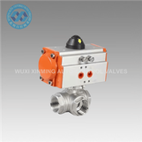
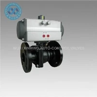
As a supplier of limit switch boxes, we offer a wide range of products to meet different needs. Our product range includes Explosion-proof Limit Switch Box, ISO 5211 Mechanical Limit Switch For Pneumatic Valves, and Valve Position Indicator. Each product is designed with high-quality materials and advanced technology to ensure reliable performance.
Conclusion
Understanding the wiring diagram of a limit switch box is essential for anyone working with industrial automation and control systems. It allows you to install, troubleshoot, and maintain the limit switch box correctly. If you have any questions about our limit switch boxes or need assistance with wiring diagrams, please feel free to contact us. We are here to help you find the right solution for your application.
References
- Electrical Engineering Handbook, Third Edition
- Industrial Automation and Control Systems: Principles and Applications